Page 85 - My FlipBook
P. 85
PROXIMAL CAVITIES IN INCISORS INVOLVING ANGLE 81
absorbed by the Avails of the cavity. Force from the direction of the
dark lines would put into operation the principles of the lever.
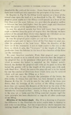
In diagram A, Fig 38, the filling would operate as a lever of the
second class upon the load at c, as described in Fig. 37. With the
gingival point angles at h the filling would operate as a lever of the
first class over the same fulcrum (a), provided the gingival outline
or fulcrum has been laid higher than the point angle and therefore
nearer the point of the application of the force.
In case the gingival margin has been laid loAver than the point
'
angle or farther from the point of impact than the fulcrum we have
a lever of the second class which Avhen figured out Avill draw an im-
mense load as shown in the explanation of Fig. 37.
In case the gingival point angles are cut more root-wise than the
gingival margin and Ave liaA'e a lever of the first class Ave must con-
sider the principles of the bent lever. When the direction of the
force (or of the resistance) is not at right angles to the arm or the
lever on AA^hich it acts, the "lever-arm" is the length of the per-
pendicular from the fulcrum to the line of the direction of the force
(or the resistance).
We must therefore conclude : First, that gingiA-al point angles
should be placed so as to extend more root-Avise than the height of
the gingival line at the proximal (that part of the gingival Avail
which is nearest the incisal is regarded as the highest point).
Second, the farther the gingival Avail Avith all its parts is from the
incisal the greater Avill be the length of the poAver arm Avith each
individual bloAv. Third, the nearer the gingival Avail is to the incisal
the less the number of directions from Avhich force may be received
Avhich Avill act upon the filling as a lever.
In order that Ave may eliminate the principles of the levers, the
step cavity, in classes tAvo and four, has been devised as shoAA^n in
diagram B, Fig. 38. It Avill be seen by the radii of the three arcs
draAvn that the increase of the surface of the filling exposed to
force does not increase the dangers of the lever as the area of the
seat of the filling has also been increased Avhich Avill absorb the force
beneath the increased surface. Again, so long as the incisal angle
in the step (at c) holds and the filling material remains rigid the
IcA^er principle has been eliminated as regards all other anchorage
of the filling.
Direction of the Incisal Angle. Fig. 39 is a draAving to illustrate
the difference in the directions the point angles take in tipping to
exit Avith various filling. Let the perpendicular shaft represent the
varying length of Class Four fillings and the horizontal bars the